Motion
micro:bit How to use a servo to make a waving hand
Description
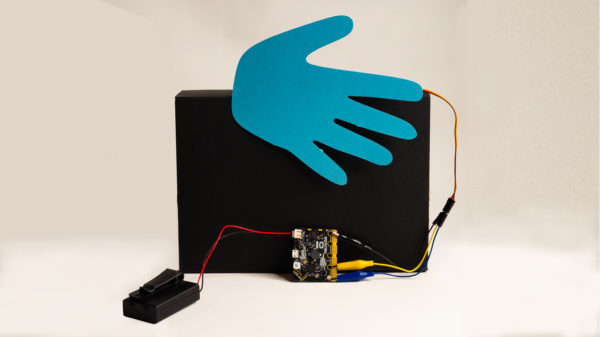
Servo motors are a go-to tool for making things move. This project uses a standard servo, connected directly to the micro:bit, to create a waving hand. The hand can be traced or printed and cut. I used a Silhouette Cameo to create the hand I used. You can decorate the hand before attaching it to the servo.Here is a video of the final project:
Materials
The materials needed to create this project are:
- micro:bit with microUSB cable
- battery pack (optional)
- TowerPro SG92R mini standard servo
- 3 alligator clips with male connectors
- Hand cutout
- Crafting supplies to decorate hand
- Hot glue or glue dots to attach the hand to the servo
- Cutout of a hand – Here is the file of the Hand pattern I used
Designing the Project
Develop a problem statement
The problem statement for this project can be as simple as “make the hand wave back and forth”. I chose to put a little more into my mine because I wanted to be able to have two wave speeds and a way to change them.Here is my problem statement:
Make the hand wave fast or slow based on an input signal. Make it stop on another signal.
Write the algorithm
My problem statement has different speeds that are triggered by some sort of input. I chose to use the buttons as the input. Another way to do it would be to tilt the micro:bit different directions to control the speed.
- When Button A is pressed;
- Wave the hand slow
- When Button B is pressed:
- Wave the hand fast
- When Buttons A + B are pressed:
- Stop waving
Write the pseudocode
I started developing my pseudocode by determining that I needed a loop and a variable to control how long to let the loop run. Once I did that, I realized I was going to need a way to determine when to stop. That is when I added the ‘To Start’ section to my pseudocode so I could initialize variables.I tested how to code the waving before I designed my method of creating a slow and fast wave. This helped because I realized that there needed to be a pause in between commands to move the servo. This gives the servo time to move before the next command is sent.Once I understood how to move the servos, I added the section on how to stop.Here is the completed pseudocode:
- To Start:
- Initialize slow variable to zero
- Initialize fast variable to zero
- On Button A pressed:
- Move the hand back and forth slowly by doing the following:
- Set the slow variable to ‘true’
- Set the fast variable to ‘false’
- Do while (slow = true)
- Move servo to 0
- Pause for 1 second
- Move servo to 180
- Pause for 1 second
- End Do
- End On
- On Button B pressed:
- Move the hand back and forth quickly by doing the following:
- Set the slow variable to ‘false’
- Set the fast variable to ‘true’
- Do while (fast = ‘true’)
- Move servo to 30
- Pause for 500 milliseconds
- Move servo to 120
- Pause for 500 milliseconds
- End Do
- End On
- On Buttons A + B pressed:
- Stop the motion by doing the following::
- Set the slow variable to ‘false’
- Set the fast variable to ‘false’
- Move servo to 0
- End On
Write and test the code
Once the pseudocode seems solid, it is time to write the code in Makecode. Makecode will simulate the servo so you can see the action without having to download it to the micro:bit.
Sample code
Here is the code that I wrote. The file will automatically open in Makecode. After the code is written, download it to the micro:bit.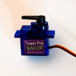
How to attach the hand to the servo
To attach the hand to the servo, use one of the horns that are included with your servo. Attach it to the top of the servo and screw it in place. Use hot glue, double-sided sticky tape, or glue dots to attach the hand to the horn.
How to attach the servo to the micro:bit
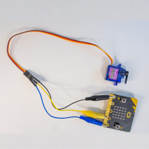 Servos have three wires coming out of them. One wire is the positive connection, one is the negative connection, and a third that connects to an output that will tell the servo controller what to do. On the TowerPro servo, the brown wire connects to the negative (GND) pad on the micro:bit. The orange middle wire connects to the positive (3V) pad. The yellow wire connects to the pin that is used to control the hand motion. In the example code included, I am using Pin 0.Use the male connector on the alligator clips to attach it to the servo. The wire colors don’t matter, but they can be confusing for students. In the photo, they are connected as follows:
Servo Wire
Brown
Orange
Yellow
Connector
Blue
Yellow
Black
Pin Value
GND
3V
0
Concepts Involved
Math used
The geometry of dividing a circle into degrees
Programming Concepts
Loops
Variables
Event triggers