Lights
micro:bit: Make a Compass
Project Description
This project uses the compass sensor embedded on the back of the micro:bit to determine direction and display it on the LED array. The compass uses the earth’s magnetic field to determine the direction of magnetic north, which varies in magnitude and direction based on the earth’s movement.
True north is a fixed point on the earth. An adjustment needs to be made to translate magnetic north to true north, and that adjustment varies according to location. This project only uses magnetic north.
The compass is a sensor that is located in the lower left corner on the back of the micro:bit. It is labeled ‘compass’.
Designing the Project
Develop a problem statement
I want to create a regular compass that helps me navigate a path so the problem statement I am using is:
Identify the current direction of the micro:bit.
Create an Algorithm
My problem statement is focused on identifying the current direction. My algorithm needs to show how I plan to display the direction. I know that the micro:bit represents direction as a degree, with 0 or 360 degrees being north and 180 degrees being south. The degree increases in a clockwise direction, so east is at 90 degrees and west is at 270 degrees. I need to establish a range of values for each direction I want to display. I want to show northeast, southeast, southwest, and northwest, in addition to the standard four directions, so I drew a diagram to help me find the ranges for the 8 directions I plan to display. Here is the diagram:
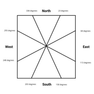
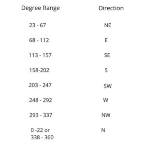
Here are the ranges I am going to use in table form:
Using the diagram and table, I developed the following algorithm:
- To start:
- Create a variable to store the current angle and set variable to zero
- Forever:
- Store the current angle in the variable
- If the angle is between 23 and 67, display NE
- If the angle is between 68 and 112, display E
- If the angle is between 113 and 157, display SE
- If the angle is between 158 and 202, display S
- If the angle is between 203 and 247, display SW
- If the angle is between 248 and 292, display W
- If the angle is between 293 and 337, display NW
- If the angle is less than 22 OR greater than 338 display N
Write Pseudocode
The most efficient way to write the pseudocode was to put the check for north as the first comparison. This eliminates the need for doing two comparisons for any other range as long as I then do the comparisons in order from low to high or vice versa. Here is my version of the pseudocode:
- onStart:
- calibrate micro:bit
- create variable called mbAngle
- Do Forever:
- If (mbAngle ≤ 23) or (mbAngle > 338)
- Display ‘N’
- Else If (mbAngle ≤ 67)
- Display ‘NE’
- Else If (mbAngle ≤ 112)
- Display ‘E’
- Else If (mbAngle ≤ 157)
- Display ‘SE’
- Else If (mbAngle ≤ 202)
- Display ‘S’
- Else If (mbAngle ≤ 247)
- Display ‘SW’
- Else If (mbAngle ≤ 292)
- Display ‘W’
- Else
- Display ‘NW’
- If (mbAngle ≤ 23) or (mbAngle > 338)
Write and test the code
The next step is to have your students translate the pseudocode into block code.
Here is the link to the Makecode file for my version for you tuse. Click it and it will open in a MakeCode window.
Here is the video of the final project:
Concepts Involved
Math used:
The geometry of dividing a circle into areas using degrees
Programming Concepts:
Decision-making using Boolean Logic
NGSS Connection
NGSS: PS2 Forces and Interactions
ESS2: Earth’s Systems
Online Resources
Use Hanging Magnets to find North